

Building a JTAG cable can be helpful to those who have inadvertently "bricked" their WGR614L. Generally, one would try the serial cable method first to try to revive the router, but if you need to bypass the software altogether and access the flash chip directly - the JTAG cable is your weapon of choice.
Here's the list of materials you will need to create your JTAG cable:
- Some cable, of course ;)
- 5x 100 ohm resistors
- 1x DB25 plug
- Soldering iron
- Basic knowledge of soldering/etc
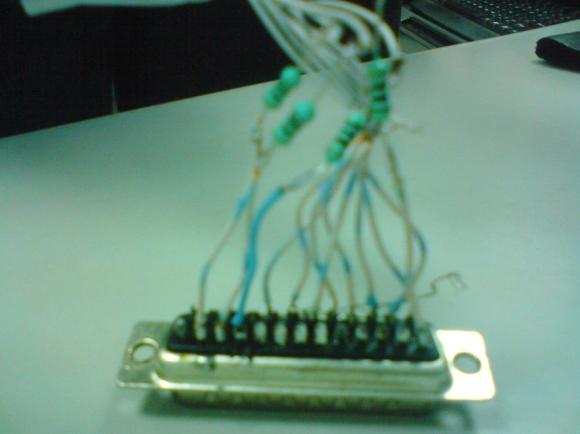
First of all, pins 18 to 25 of the DB25 plug (i.e PC parallel port connector) are shorted and pins 2,3,4 and 13 are connected with 100ohm resistors. This much is needed for the DB25 plug.
The next step is to connect this DB25 plug with the ribbon cable that we have. This connection has been shown below:

Here are the pinouts:


As seen from the above figure, pins 2 to 10 of the JTAG connector are shorted and connected with pins 18 to 25 of the DB25 plug.
Given below are the different views of the connection between the ibbon cable and the DB25 plug:
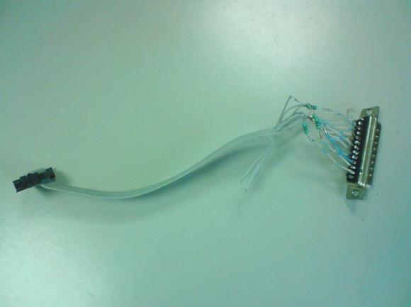
This is how the cable is made, but it can’t be used directly. Here's a view of the completed cable:
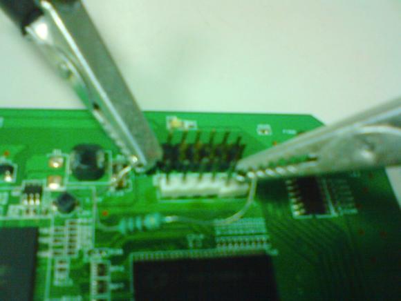
To get it working, we will need to connect the Vcc of serial on the board with the Vcc of the JTAG header on the board with a 100ohm resistor, as can be seen below.
Now, you should be able to JTAG!
NOTE: This cable and setup have been used for TJTAG-v3 available at:
http://www.dd-wrt.com/dd-wrtv2/down.php?path=downloads%2Fothers%2Ftornado%2Fj... /> on Netgear WGR614L .
Please post here or in the forums if you have any questions on how to JTAG!
greets, dominic
Can you be more specific on how and on wich pins the 3.3V connection has to be made. The photo is not clear enough to help me out with it. A diagram would be more helpfull or even a better disciption in the text will do.
As a remark i'd like to mention that it is better to solder the resistors direct on the DB25 connector with as short leads as possible. You'll get a more compact unit and less prone to short circuit.
Check out the photos in this article, it shows you exactly where to solder the leads from the cable:
http://www.myopenrouter.com/article/10341/Recover-Your-WGR614L-Using-a-S...
This is my problem, i just want to know where the 100Ohm resistor from the last photo in THIS article is connected.
I searched the internet for which pin the VCC is on the JTAG connector and could no find a good answer. As far is i can see the restistor is clamped on pin 1 of the serial connector. But the other lead (left on the photo) from the resistor is connected to...?
Guys, do I have to use 5th resistor to connect PIN2 (of 12) to PIN6 (of 6) for WGR614v8?
For anyone needing clarification - The 5th resistor connects pin 1 of the serial port to pin 1 of the JTAG port.