
Hopefully, you will never have to do this, but if you are like me and like to work on the bleeding edge of technology - sometimes things happen. (Of course, you might just enjoy getting down to the core with your new serial console, too!)
So, you've "bricked" your WGR614L, either through too much tinkering or just a fluke. You may have tried tftp through your network cable, you just can't get a ping or for any reason can't get it going again. Rather than panic, you can access your router by using a serial console!
There are several tips on this board that talk about how to do it using Linux, but like me, you may not run Linux, or don't want to have to setup a computer to do so... so here's how you do it using Windows. (Remember, the hardware setup is the same whether using Linux or Windows.)
Step 1: Get the USB to Serial Converter
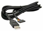
First you need to get a USB to Serial converter. You can get one here at Mouser.com. This cable allows you to connect to your computer's USB port.
This is what the cable looks like:
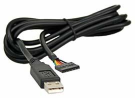
You must make sure that you get the correct one that operates on 3.3V. If you buy the wrong one, or try to convert a standard USB connection, you will fry your router, as standard USB connections operate at 5V.
UPDATE 10/27/2008: The specific cable mentioned is no longer available from Mouser Electronics. Member UncleBic has located a reseller who stocks a similiar cable here. We welcome user submitted links of resellers who can provide cables that work for this project.
Step 2: Connect the Cable to Your WGR614L
The USB side of the cable is easy to figure out. The other side, the business end of the cable, is not quite as easy! You'll need to actually connect the wires from the cable to the router directly.
First, you'll have to know where to connect the cables. Remember, as Mr. Screwdriver and his sidekick, Mr. Soldering Iron always say, this will definitely void your warranty - although you may already have done so by bricking your router with a third party firmware, of course.
This is also not for the tech-scared or otherwise faint of heart. You may need to solder some connections, and in the least, take apart the router casing.
To get to where the cable needs to go, you need to take the board out of the casing. To do this, you have to remove the rubber feet off of the router. This is done by simply pulling on them and they pop off.
Then you need to remove the 4 screws that attach the housing. You will need a small torx bit for this, or as I do, just improvise. :)
The casing without the feet looks like this:
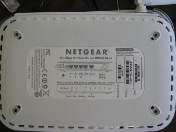
Just take the screws out, and it will come apart easily.
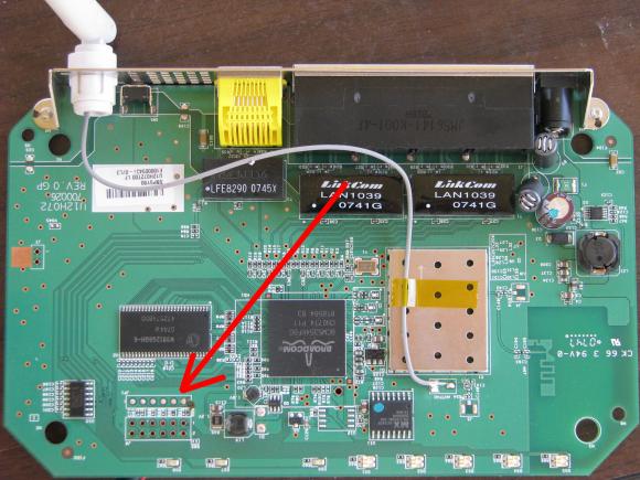
You will then have just the motherboard of the router.
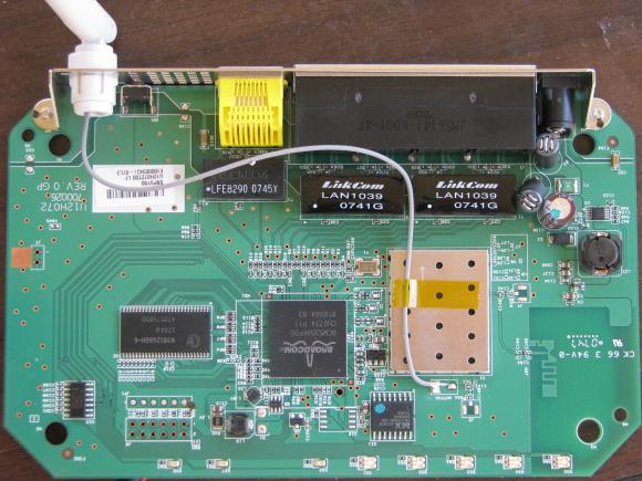
Now you need to find the JP1 connector, pointed out by the red arrow.
Now, pay attention - here comes the tricky part. If you're lucky, there will be connectors here to simply plug your USB connector into. However, most are as shown, and there will be no way to plug into it.
This is a close up of how it looks, without any connectors available:
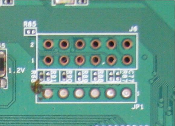
You will notice there is a number 1, just above the JP1 label. This tells you that the #1 pin is on that side.
Here is the Pin Layout
Pin2 is the RXD to Receive Data
Pin 5 the TXD to transmit Data
and Pin 6 is the GND or Ground
So you would connect the TXD of your USB cable to the RXD pin on the router and vice versa for the TXD pin on the router.
You do not need the other pins
What you'll need to do now is to solder or connect 3 cables from your USB to Serial converter, to the router.
You need to connect the black wire from your cable to the number 6 pin on the router.
Then connect your yellow wire to number five, and the orange wire to number two.
In my case. I just soldered them directly:
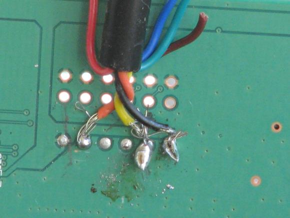
I know, I know... it's not the best solder job, but I had my protege do this one. Have to learn sometime. :)
Step 3: Plug In the Console and Load the Driver
Now that you have connected the wires to the router, and can plug the other USB end in to your computer, you'll need to get the serial to USB driver.
To get the correct driver, you can go to this site and download the correct driver for your system.
Once you have downloaded the driver, reboot your computer and let it come back up.
Then, you will plug in your new USB to serial converter and it should get recognized by Windows. If not, you may have to install the driver manually.
Step 4: Download, Install, and Set Up the Console
The next thing you'll need to do is get some kind of program that will allow you to talk to your router via a command console. I recommend the Putty program, which is available here.
Just download it, install, and then set it up - you will need to adjust settings in the "Serial" portion.
First, select the Serial port, and then the rate:
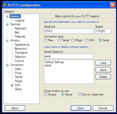
You'll have to select the Serial icon, and then enter the correct information.
In my case, the port that my USB to serial connector uses is COM3. So, you would enter that, and then the speed. The connector uses a speed of 115200. Don''t try anything else, or you won't be able to connect properly.
Then, you need to go into the serial settings and make sure you are on Data bits of 8, Stop bits of 1 and Parity and Flow control is set to none.

Now you should be ready to rock and roll!
Step 5: Set Up The Console
Here are the steps to do this - remember that it's very important that you complete the steps in this exact order!
- Make sure the power to the router is unplugged.
- Hook up the network cable from your computer to the router.
- Setup your computer to a static IP address. If you don't know how to do this, in XP, you go to the Network connections setting. You will see this window.
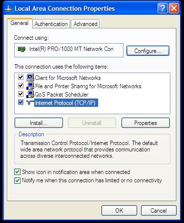
- Click on the (TCP/IP) Protocol and then select Properties. You will now see something like this:

- Set the Default Gateway to 192.168.0.1, the subnet mask to 255.255.255.0, and then the IP Address to anything that does not end in .1
- You also should set up the preferred DNS server to 192.168.1.1
- Click on OK, and you should be good to go there.
- Now, you need to get the latest OE firmware. You do this by going here and downloading it. Don't try an aftermarket firmware like DD-WRT or Tomato just yet. Use the original firmware this time, you can upgrade after you get your router back online.
- Make sure you put the file in the root or main directory on your computer, also known as the C:\ directory.
- Now, run Putty. You will get a window that opens up and you won't see anything happening in it... don't get scared, though, 'cause you probably haven't plugged in your router yet!
- Now, get ready for the fun part!
Step 6: Reflash the WGR614L
- Make sure the Putty Window is in the front.
- Plug in the power to the router.
- As soon as you plug in the power, you have to hit Ctrl-C. You may have to hit it a couple of times.
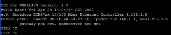
- If you are successful, you will see this message:
- Now go to your Windows Start > Run command and type in "cmd" you will be presented with a DOS style window that says something like:
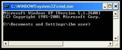
- Then type in "Cd\" This will put you to the C:\ directory.

- Hopefully, you've saved the firmware file in your C:\ directory as wgr614l_1_1_2_1_0_23_na.chk.
If not, for this article, make sure you have saved it with the same filename and in your C:\ directory. If you have saved it under a different name or in a different directory. You will need to go there and change the filename. - Go back to your Putty window and type in "tftpd" You should now see it say:
START TFTPD SERVER
READING:: - Go back to the CMD window and type in
"tftp -i 192.168.1.1 put wgr614l_1_1_2_1_0_23_na.chk." - In the Putty window you should now see:
"Loading..................................."then...
"Programming...
Everything in the Putty window should look something like this:

You should not power cycle the system before completion of the flash. It should take about 5 minutes or more.After completion of the flash, Once done you should see the following message:
"Write len/cksum offset @ 0x0038FFF8...done"
Then, your WGR614L should automatically reboot with the new firmware image.
Now, you should be up and running! Pat yourself on the back! You'll be able to disconnect the cable and run your router as normal.
Quick Links
View Downloads and Firmware for the WGR614L | View Articles and More for the WGR614L
So what is the pinout if I dont buy that cable and decide to go with a usb-rs232 adapter?
Whatever cable you buy should have something with it that shows the TX, RX, GND wire colors. If not you will have to contact that company and get the information.
I understand that but what goes where on this board? The RX, TX and GND are not labeled in the tutorial! All that is listed is orange, yellow and black and that can change with cabling.
Gotcha now, thanks for the heads up. I added that to the article.
Here is the Pin Layout
Pin 2 is the RXD to Receive Data
Pin 5 the TXD to transmit Data
and Pin 6 is the GND or Ground
Cool, thanks!!! Could I just use a straight through RS-232 and a DB9 pin header with leads solderd into the JP1? Or would the voltage be too high?
The article should be corrected... "standard USB connections" do not use 12V, they use 5V. Maybe the original author meant to say that standard _serial_ connections use 12V?
Good catch. Fixed.
Thanks
What are all those other pins for? Is there a second UART available? What about the eight GPIO lines available from the Broadcom SOC? Can we get to those via the eight LEDs on the front of the box? Where is the JTAG connector?
Dude, Wish I could help you with those questions but can only give out the info that is published. Are you trying to do something special or just curious?
Is it possible to do this process with a standard RS232 serial cable? I had a standard serial header which I soldered to the board with the appropriate TX/RX/GND config from above. I have traced my cable to ensure it is flipping the the TX/RX as it should be.
At one point it was working and I could see the board going through the boot process, and the firmware I had uploaded was having an error, which causes the router to reboot.
However, CTRL+C would never drop me down to the CFE bootloader to start up TFTPD. So I tinkered with it some more, thinking maybe I had a bad solder or something keeping me from getting input set properly, but no dice.
Now when it goes though boot I basically get garbage on the screen equivalent to where it used to give me legible data. It also used to say "Loading" then print periods to the screen to indicate progress. Instead of periods, I now get "4"'s.
Buy using a straight serial cable did I fry something?
THANKS NETGEAR, for making me have to interrupt my life and jump through all these fucking hoops to recover the damage that you did in 10 seconds with your scam piece of shit firmware
THANKS NETGEAR, for making me have to interrupt my life and jump through all these fucking hoops to recover the damage that you did in 10 seconds with your scam piece of shit firmware
FOR THE LOVE OF GOD DON'T DIRECTLY CONNECT AN RS232 CABLE!
Ok, sorry to shout, but you will definitely brick the router!
The reason is, the connector on the board are TTL serial (5v) and the RS232 is 12V
That would of been good information at the top of this post!
First let me say that I'm new here and have to bow down to all of you who do all of the code stuff. I'm just starting out with a WGR-614L and have been using the "regular" WGR-614's for a while, I've actually gone from despising them in about version 3 or 4 because the setup forced using the wizard, to now where it's the first router I recommend.
If you click on the slide show it will link you to my PicasaWeb album. You'll notice that, I too, am not very good at soldering. Hopefully I haven't really ruined my router. After loading DD-WRT I was having some trouble and eventually I couldn't get back into the setup. Hopefully after using the serial cable I'll be back in business. After all it's the reason I came to this page. I figure I'm bound to screw it up again so this little project seemed like a natural. I'll post what I've done at the page linked to at the bottom as soon as I can.
The forum page where I learned about hard wiring a serial cable. - My hat is really off to BrandonC.
http://www.myopenrouter.com/article/10341/Recover-Your-WGR614L-Using-a-Serial-Console-Windows/
Then I did some searching for a way to have a plug that would come out of the router and not a permanent cable hanging out.
This guy was using a cable that would do just that, but the place he linked to was out of them.
USB Serial cable - http://www.themailshack.com/WRTSL54GS/2007/04/usb_serial_cable.html After reading about that cable I had exactly the same idea he did. Had I not been in such a rush, I would have nosed around his site to see his outcome (http://www.themailshack.com/WRTSL54GS/2007/04/serial_upgrade_complete.html). It didn't really matter, since we're talking about a WGR-614 here and not a Linksys WRT.
I ordered my cable from a shop in the UK (shipping from Oregon, USA), and have to say that they're very helpful. I wasn't sure about the internal wiring and they fired back a quick response to show me(http://www.ftdichip.com/Images/TTL-232R-AJ%20pinout.jpg). Very nice, thank you Andrew Cumming, so I ordered from them right away.
http://apple.clickandbuild.com/cnb/shop/ftdichip?productID=70&op=catalogue-product_info-null&prodCategoryID=47
Slideshow - http://www.viclovan.com/usb2serial_plug_project.htm
Individual Pictures - http://picasaweb.google.com/UncleBic/20080901NetgearWGR614LSerialToUSBPlugProject#
Radio Shack - 1/8" Stereo Panel-Mount Audio Jack (2-Pack) # 274-0249
http://www.radioshack.com/product/index.jsp?productId=2103452&tab=techSpecs
Scosche - I bought this at Wal-Mart but couldn't find a direct link to it.
Car stereo Wiring connector
"84-Up Universal Import
(part#) IM01A
Vic
Update: My cable project worked great and I got my router up and running DD-WRT with "DD-WRT v24-sp1 (08/08/08) mini (SVN revision 10152)" since I did the project. The router runs smoothly and allows me to have mutiple SSID's. I can share one with the little neighbor girl and I don't have to worry that she can "see" my networks (I also have a SmoothWall running after of the wired part of the DD-WRT). This set up allows me to work on client computers that are totally infected with all sorts of nasties and not worry too much about infections across the networks.
Update2: If you want to see the individual pictures click here
to be taken to the picasaweb page. There are captions with explanations
for some of the pictures as well. You are also welcome to use Picasa
to download the pictures if you want. It's easiest just to download
the whole album at once. Hopefully this will help with your own mod.
If you flip your router upside down, you should have a sticker on the bottom that has the mac address on it.
If you need the mac address for a network card, it should be on the card itself.
Thanks a lot. Just recovered one, now for the other. Very good article.
The Mouser catalog link shows the DLP-TTL232R-3V3B serial cable as obsolete and not available. Are there any alternatives?
If you check my post in this thread, http://www.myopenrouter.com/article/10341/Recover-Your-WGR614L-Using-a-Serial-Console-Windows/#684, you'll see I had the same issue. I did find one that worked great for me. I went a bit further with the cable installation. The one I used can be ordered here, and that same site has other types of cables that will work also. Just make sure you get one with the "3.3V levels", so you don't burn anything out, as mentioned above. One note about the place I ordered from, I had time to wait since I was adding this router into an existing network so I didn't need a rush. If you do you'll want to check the shipping options, they're not close and rush shipping may cost a lot or might not be available, I think mine took about a week.
Good Luck!
Vic
Thanks for the very explicit pointer. I was not thorough enough in reading through the other postings. It's another reason to feel like a dinosaur.
No need to feel old. This page is getting a bit long. I'll try to contact the OP and see if he'll update his links.
Vic
Hello everyone,
Thanks for your posts. It looks like the specific model of cable that's mentioned in this article is obsolete. I'm going to find out what would make suitable replacements, then update the links in this article. Thanks to everyone who has brought this to my attention.
Pete
I've already done some of the leg work on that for you. Check out the links in my posts. I found some that were priced fairly and got delivered quick as well. The staff was also very fast with a link to a picture that showed what wire was inside the cable so I could connect it to a jack and a plug. They also have the other types of cables described in the OP's article. The difference is that I built in a plug so there is no cable hanging out of the router that can't be easily removed.
Other than that, happy hunting!
Vic
That's great, I'll update the article with this link for now, and update with more as I find them. We also welcome anyone to update this thread if they find a retailer selling a cable that will work.
Thanks again! Pete
Hi
I believe there may be a suitable cable from a US source. Bear with me on this - I have diabetes and use a software program and cable to download blood sugar readings from my digital meter. The cable looks for the world like the one that you mention - miniature plug with three connections on it. It could be something completely different but I don't think so. The meter is the OneTouch Ultra2 from www.Lifescan.com (be careful of the meter model number). The program (OneTouch diabates management software) and cable cost around US $30 + shipping. Unfortunately I am away from home until November 8 so I will not be able to check this out in more detail until then. I am open to suggestions on how to test this.
It took me a while, but I eventually found a supplier of USB to low voltage TTL adapter cables in the US who accepts payment via Paypal. Doh -- looks like Mike and I were on the same page there, that's the same place I found.
I updated my post to include a couple of new links, including the jack from Radio Shack. I couldn't find any better or cheaper wire links with the right colors than the wiring adapter. I also updated the captions on some of the pics in my picasaweb album.
UncleBic,
Now that you have new links and new pics I think it would be great to see a comprehensive article on this. It is very cool.
There is a way you can submit a full article here that is pretty easy to do. You should see a link on the right side that says "Submit Article" and you can then do so and after review it could be posted to the site.
Hey,
For anyone who is reluctant to spend that kind of money on a serial cable.
After a bit of research, I found a suggestion that a Nokia Model CA-42 cell phone adapter cable works and is the appropriate USB to 3.3v TTL needed.
There are tons of clone cables available on EBay for less than $5.
Such as this one: HERE
It has the large housing on the USB end suggesting there is a chip in there and it's not just straight to USB connection.
Can anyone verify this?
Source: HERE
what do you guys think of this as an alternative to the USB to RCA miniplug? It is also 3.3V, but it's a USB-mini.
http://www.pololu.com/catalog/product/391
Pages